
This is a post where I talk about the projects of The Graphics Codex by Morgan Mcguire and present my results for each one. I was having a bit of a trouble focusing on one thing at a time because I wanted to do so many things! So, I decided to end my struggle by following a specific “curriculum” which has concrete goals to narrow down my selection. Every project requires to read up on specific subjects that are more beginner oriented but it is a nice refresher of the basics.
I talk about the strengths and weaknesses of each project, what I’ve learned and what I’ve achieved following the guidelines of each one. I hope to inspire anyone who happened to stumble upon this post and manages to finish it.
For the watered down version with less text and all the screenshots, please visit my Github page which, also, has the source code of all the projects.
1. Cubes
The “Cubes” project is the first one in the series and serves as an introduction to many things such as coordinates systems and positioning in 3D space and the G3D Innovation Engine. This is a very good starting point to learn Computer Graphics because the basic rendering is already implemented, there is a streamlined way to add GUI elements and provides the way of structuring the code when working with a real-time engine.
The pros of this project are:
- It is a great introduction which doesn’t require any previous knowledge; only C++ familiarity.
- Already implemented controls (FPS camera), debug GUI and camera effects adjustments.
- It touches on procedural generation without being too complicated (with the generation of a staircase).
The cons of the project are:
- The bloom effect is bugged and it doesn’t work well with spot lights. Since it is enabled by default, the reader needs to fiddle with the debug GUI and disable/enable everything until they find the culprit.
- The documentation on how to write in the .Any “language” doesn’t refer to every object and can be a huge pain for beginners. The only hope is to scour through the samples in hopes of finding something that fits our needs.
The final “assignment” of this project was to create a complex scene using only cubes. My “deliverable” read an image and created a cube grid where each cube corresponds to one pixel and the cube’s height depended on the luminance of the corresponding pixel. Below are two renders of a scene rendered in G3D.
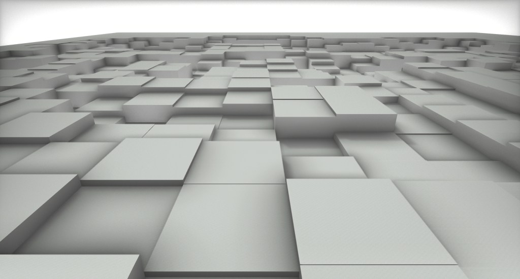
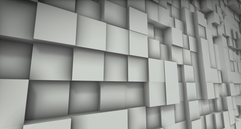
Overall, I think it is a great learning experience but the cons become more important the less someone is experienced with C++ and reading documentation of software. It should, at least, mention some sample files in the G3D repository to introduce this way of thinking and searching to the beginners.
2. Meshes
The next project speaks about topology and expands on procedural generation by requiring the creation of a wine glass. The reader should first create a cylinder, then create a heightfield and, lastly, create a wine glass using only it’s contour from a half cross-section. My “deliverable” for the Cubes project was like a heightfield but with many more objects and way more image sampling because it is a recreation of the image with cubes (it can get out of hand with high resolution images and G3D didn’t like that).
The pros of the project are:
- It speaks about topology and when someone finally understands that a mug is the same as a torus topologically because they have only one hole, a very big “AHA!” arises.
- Procedural generation.
The cons of the project are:
- The setup of the existing GUI is not “correct” and the reader needs to debug it in order to place more items in the same style. This is something that I would normally classify as a “pro” because it is a learning experience but the reader already has many things to keep track of; putting more obstacles does not help.
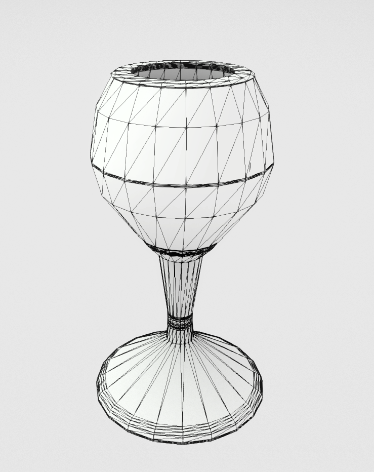
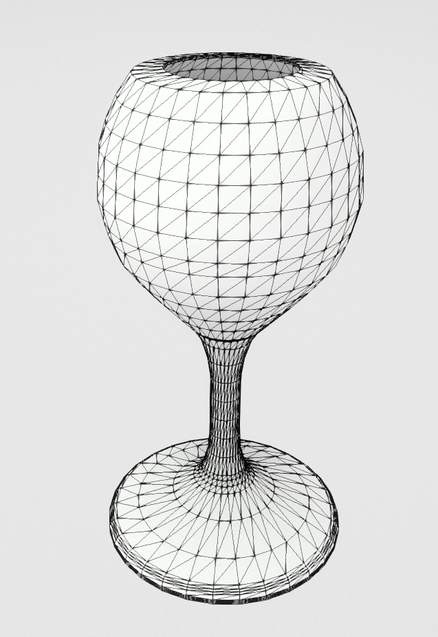
The requirement for the wine glass is that the glass should be created only from a contour and an optional GUI element would be the number of rotational slices to generate. Since I didn’t want to give the numbers by hand or interpolate a Bezier curve and import the points, I decided to (again) use an image as input. The specification for that image is that it has to be grayscale with black indicating point of mass and white indicating surrounding space. After generating the wine glass, I had to present it in a stylish way.
For the generation of the glass, I simply read the image lines to find start and end points of mass and then translate them to a normalized system to preserve the aspect ratio. The initial results were encouraging but I didn’t like that there was too much generated geometry (one ring for every pixel line). So, I added a “Quality” slider which translates to a distance and an angle criterion that evaluate if a ring should be inserted or not. The lower the “Quality” the less rings are inserted and the higher the “Quality” the more faithful is the result to the input. I ended up liking the lower quality results more because they were cleaner.


From left to right: i) the grayscale image input, ii) the raw result where every pixel line generates a cylindrical ring, iii) a low quality result with the naive angle criterion and iv) the low quality result with the distance and angle criteria.
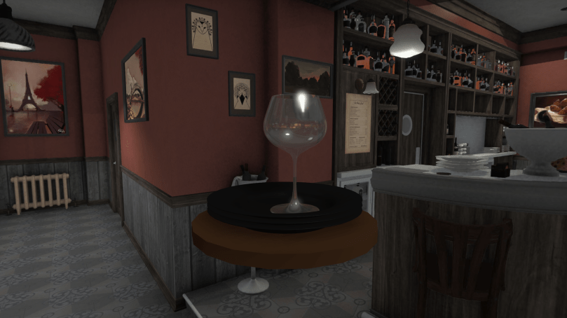
I decided to produce a more sophisticated presentation for this project with a more refined glass along with some plates and place them in a bar setting. The plates are generated with the same method as the glass. Below are the render in G3D, the input images and the resulting meshes.


3. Geometry Design or How I spent a day to track a bug that turned out to be a feature.
Having finished the fourth project “Rays”, I returned to this one to support Instancing on top of the previous deliverables. The implementation was not hard but the way the project definition is worded makes it extremely difficult to find the exact G3D classes to use; and this wording is what made me spend that day for the feature. The way Instancing was implemented is:
- Keep one version of each model in the scene.
- For each Instance hold:
- It’s Axis Aligned Bounding Box.
- It’s TriTree which is a CPU tree with all the model’s triangles.
- The model’s inverse transform – needed to convert the rays from world to object space.
- The model’s transform – needed to convert the hit surface information back to world space.
- When a ray needs to be intersected:
- Intersect the bounding box of every instance.
- Intersect the triangles of every model whose bounding box is intersected.
With the simple addition of bounding boxes for the models instead of manually intersecting every triangle the performance boost can be insane depending on the complexity of the models. Having to load each model only once really helps with the memory footprint of the program and we can batch rays per model and triangle in order to have better cache coherency. Another needed improvement is a Binary Space Partitioning (BSP) tree to hold all the bounding boxes and, again, intersect only those needed.
The pros of this project are:
- The reader can learn about much needed optimization techniques. If they are fiddly, they will have to debug the same thing as I did which, in the end, is a good way to learn about how G3D does things.
- Depending on the project selected, a range of computational geometry problems can be tackled which are not too hard but not too easy either.
The cons of this project:
- The wording. Starting with the Rays project, there are certain things that are asked to be implemented and some rendering of expected results. The Rays project presents renderings with shadows from Area lights which are specifically excluded from the required implementation. This project required to make Instances for each Model but as will be shown below, we needed to make instances of Lights (or manually intersect with the Lights) otherwise the results would not be the same as the Rays project.
And now about the feature.
Looking at the next slideshow, the first image is what is generated with 1 indirect ray from the Rays project and the second image is the result with 1 indirect ray from this project. The first thing that can be noticed is that the light is getting bigger and I noticed it too now that I’ve made the two results fade between each other. The difference I noticed at first and decided to investigate is that the noise in the second image has an orange hue in some clusters.
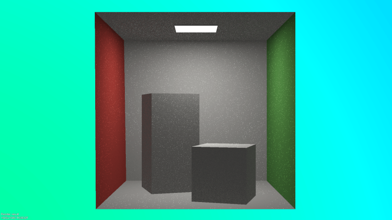

The first thing I thought is that I have messed something in the ray calculations. Indeed, I was not converting the hit surface information back to world space but it didn’t solve the issue which lead me to inspect the value that these pixels are reporting with the G3D image inspector. These pixels were reporting a very strange hue which I couldn’t justify based on the lights in the scene.
I believed that it was, again, a rendering error due to some mis-transformed variable from object space. I removed each part of the rendering equation, biradiance and the scattering density function and it seemed that the biradiance was, somehow, the culprit even though the variables that were being fed were exactly the same. I started stepping into every G3D lighting function that was called in order to find that mis-transformed variable but to no avail. Alright then, if the equations are correct then the scene is not correct.
A new round of stepping into the function with the debugger was underway in the part of G3D that loads the scene and after some hours I saw it: the model that was being loaded contained an emissive surface; but why is it different from the other light? Why does it have an orange hue? Recalling some images of the Cornell Box and after checking online, the original model has a light with an orange hue, like below.

So, the model that was loaded contained a surface that has white diffuse but orange emissive color. This is done in order to simulate the over saturation of the real lamp on it’s plastic part at the top of the box and emit the correct light in the scene. Primary rays that hit the surface will report the color white but some indirect rays that happen to have a low scattering factor will get the orange hue because the factor affects only the diffuse.
But what went wrong? This is where the wording of the project comes into play. This particular problem occurred because the project mentioned that we need to create an Instance for each Model of the scene and discard Lights, Cameras, Particles and models that can be animated. BUT some G3D::Light objects can produce triangles, such as area lights, in order to intersect them.
The Model that is loaded contains an emissive surface but the Scene that is loading that model contains one extra area light that is placed at almost the exact same position as the emissive surface, effectively covering it. Since I loaded the triangles from the model only, that surface had the correct diffuse color (fully white) but some indirect rays were carrying an orange hue because they happened to intersect it. Including the G3D::Light geometry in the computations, the noise went back to the original behaviour.
From the project deliverable point view, the result with the orange hue is the correct one because it does what is asked of it: keep only the models. From a correctness standpoint based on what the Scene contains, the Rays result is the correct one.
Personally, I found it a great mental exercise but it highlighted the problems of the project definitions that started with the Rays project. Let’s hope number 5 improves that.
4. Rays
The rays project asks of the reader to implement a CPU ray tracer. The features that will be implemented are:
- Multi-threading (easily implemented through G3D’s API).
- Shoot rays that pass through the center of each pixel and calculate their Radiance.
- Implement ray-triangle and ray-sphere intersection. The algorithms are discussed in the reading material and an optimized version of the ray-triangle one is provided.
- Perform α-testing on the triangles.
- The illumination must take into account:
- The emitted radiance,
- An ambient term,
- Direct illumination from point, spot and directional sources,
- Perform shadow test for lights that can cast shadows.
- Indirect radiance by sampling random directions around the normal of the hit.
This is the first project that requires a stronger will to complete because of the nature of the bugs and pitfalls that may be encountered. There are many artifacts due to the floating numbers precision and the implementation requires a lot of back and forth until the results are satisfying.
The pros of this project are:
- The reader gets to learn so many new things and how the light needs to interact with every surface to produce what we see as color. It’s very enlightening.
- The study material contains references of the very first papers in the research field and the curious reader will appreciate them.
- The exercise of deriving the intersection algorithms helps the reader develop intuition and skills for the next intersection algorithms they might need.
- It is a good challenge to complete and seeing the beautiful images at the end is a great reward for the effort.
The cons of this project are:
- The guidance it provides can be very lackluster for a beginner and a lot of time can be “wasted” on things that could have been explained clearer. This project can very hard to implement without some guidance.
- Some of the “results” pictures cannot be reproduced with this project. The Cornell Box scene cannot have dark shadows because the Area light is not marked to cast shadows and the shadowed parts receive direct illumination. Only with a lot of indirect rays will these areas appear darker.
The Advice section should be re-read every time the reader is stuck because they might have missed something valuable. I believe that this is going to hold true for all the remaining projects.
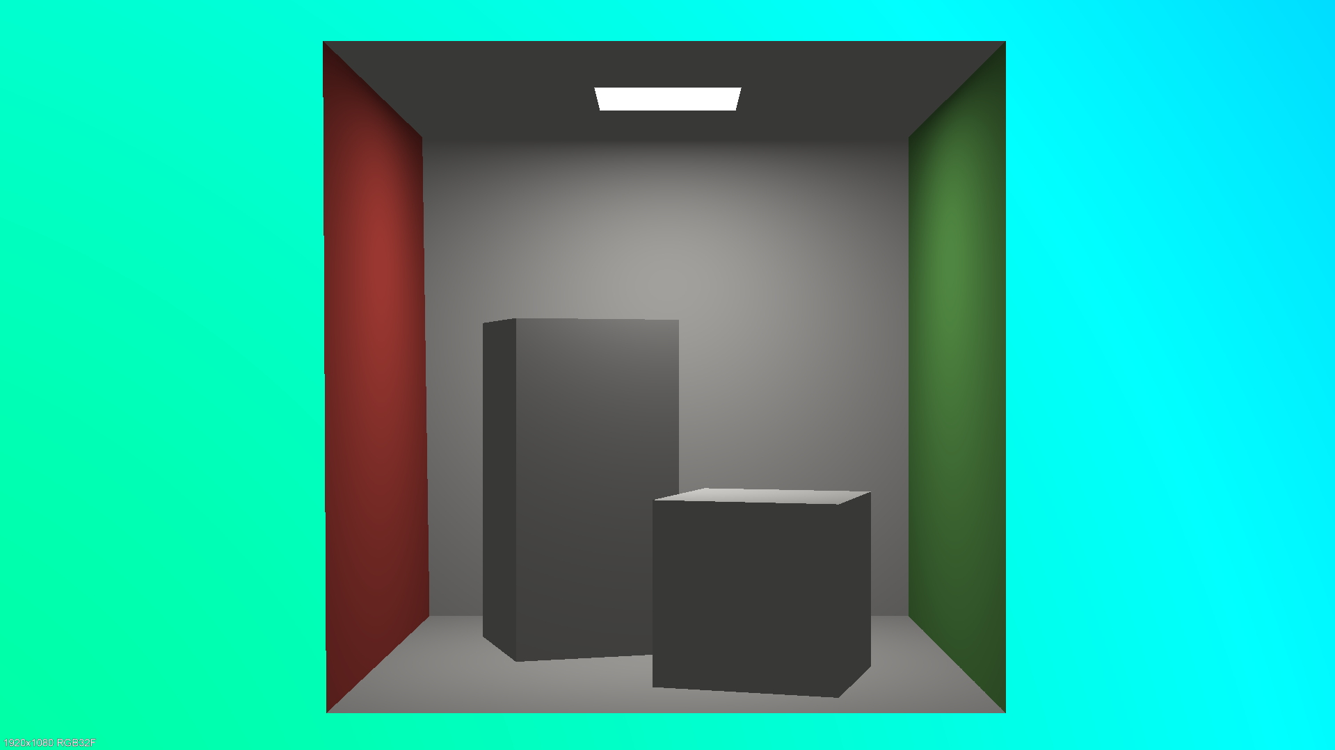
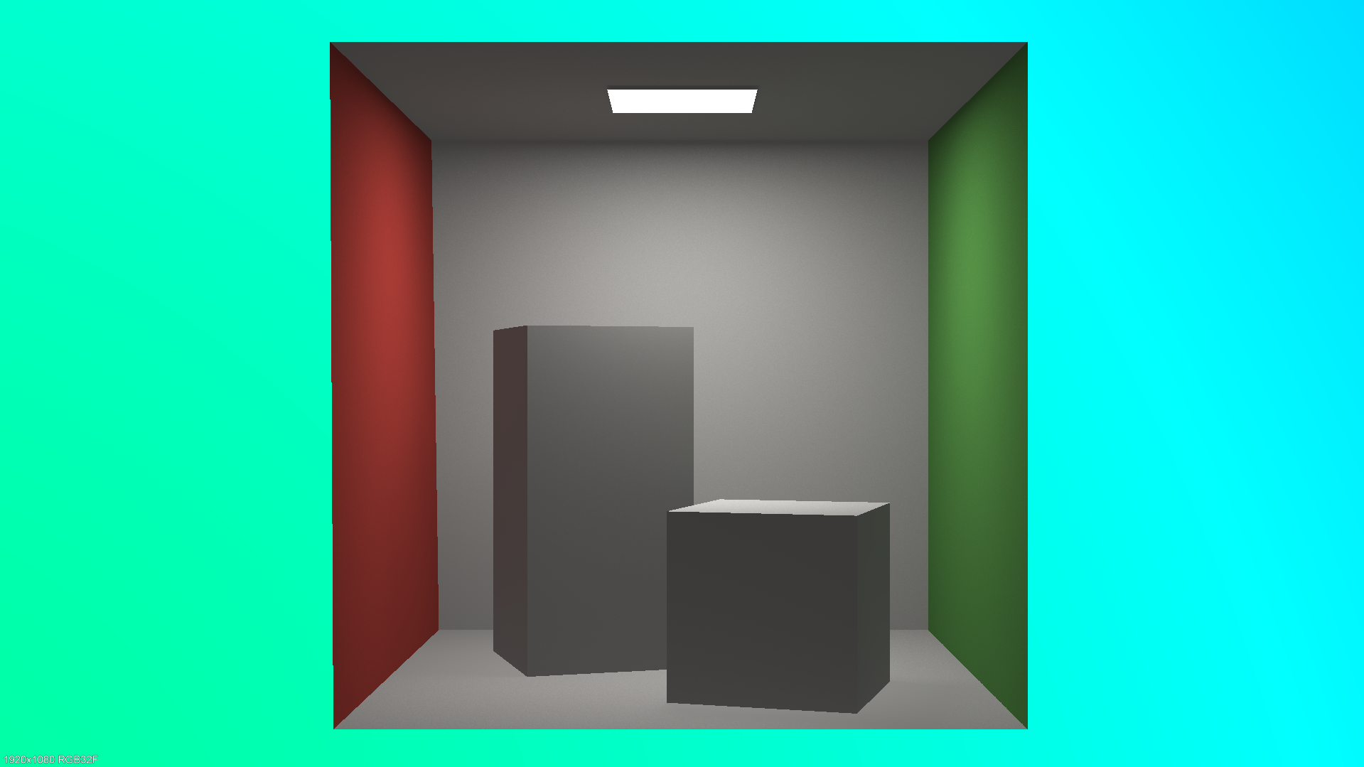
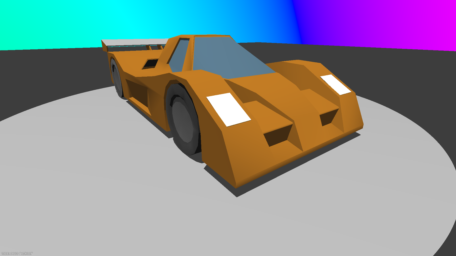
Below are the results I got for the “Cornell Box” and “Test Scene” G3D scenes. The first of each is rendered without indirect and the second with 2048 indirect rays from the surfaces. All the rays are one-bounce rays. The rainbow sky doesn’t affect the colors of the scene; it’s just a random hue based on the direction of a ray that doesn’t intersect anything.
Cornell Box: the indirect rays provide a more accurate representation because we can observe: a) the left side of the left rectangle has a red tint, b) the right side of the right cube has a green tint and c) there is a slight shadow at the bases of the rectangle and the cube. The shadows should be more prominent but we don’t perform correct shadow calculations for area lights in this project.
Car Scene: the indirect rays are not improving the image too much except for the cavities which are brightened and more details can be observed. The image with the indirect rays has noise because the car’s material is metallic and the finiteScatteringDensity of it’s surfaces is very high. Blender has a setting to reduce that source of noise.

The time it took to render the scenes in 1920×1080 with 2048 indirect rays was: 4m34s for the Cornell Box and 3h45m30s for the Car. Analyzing the performance for the hotspots of the computations, 50% of the time is spent in the ray-triangle intersection function. The code of this function is already optimized and can’t take it any further and considering that it takes literally half of the time, there are just too many ray-triangle intersections performed. The optimization for this case is to reduce how many triangles we check for intersection. The first step is to have bounding boxes around the each model to intersect these first and then build a BVH for the whole scene. We should perform the expensive calculations only when there is no other option.
5. Paths
This is the project that pieces everything together to finally produce beautiful images without waiting days; but still, some hours will be required. In this project, we had to:
- refactor the code from the Rays project into a more scalable solution based on the ray count,
- support multiple transport paths per pixel to reduce noise (but have fixed maximum path scattering depth),
- implement light importance sampling for point lights and spotlights,
- try to figure out why the results of our program don’t match the correctness images provided.
The pros of this project are:
- The reader gets to implement massive optimizations and they do so by changing their frame of thinking. (See next about loop inversion).
- The theory for the project is the fundamentals of path tracing and the writing of the related chapters is excellent.
- A lot of debugging needs to be done to find that a division should be a multiplication. Great learning experience in debugging.
The cons of this project are:
- The same as the Paths project.
To make the Rays project more scalable, we had to reduce the time of the ray-intersection handling because it was taking 50% of the time. This was done by batching the rays together and casting them in one function call. Instead of revisiting the intersection acceleration structure every time we needed a new ray cast, we cached it and then casted them all together.
The main loop of the program was changed and instead of looping for every pixel and then for each scatter event of that pixel path, we looped for every transport path and then for every pixel. This way, we sampled all pixels at the same time for the same transport path and the same depth at that transport path which enabled us to group the rays into meaningful batches that could use optimization flags from the G3D intersection API such as COHERENT_RAY_HINT.
The light importance sampling was performed to allow the insertion of many lights without taking a huge hit in performance with every new light added. This is done by measuring how much each light affects a surface and then choosing only one of them for the shading. The shading result is then weighted to provide a sort of remedy for the fact that we only used only one light.
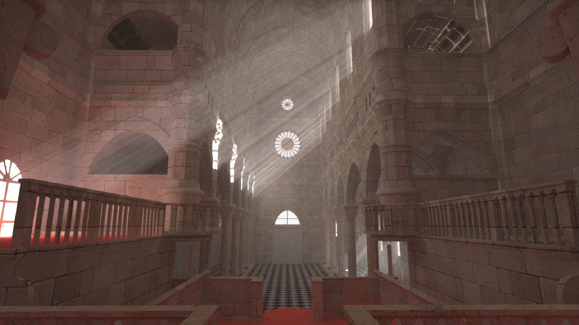
Below you can see some results from my final code.


The “Breakfast room” scene at 1920×1080 resolution, 1024 paths per pixel and 6 scatter events max took 1 hour and 7 minutes of rendering time. The “San Miguel” scene at the exact same specification took 1 hour and 3 minutes to finish. The “Sponza” scene at 1920×1080 resolution, 4096 paths per pixel and 6 scatter events max took 3 hours and 54 minutes to render.
The last thing that I had to realize and implement to match the “correctness” results that were presented by the author at the end of the project is some jittering of the point lights and spotlights. This was required to prevent very hard shadowing at the end of the light’s reach.
Overall, it was very satisfying to finally be able to intersect such large models and emulate the effects of reflection and refraction. Again, this project lacks a lot of small things that the reader have to figure out themselves since there is no one to ask because the information presented was designed for a class. Nevertheless, moving forward without help is what will truly make this project feel like an achievement. (Don’t forget to peak a bit at the G3D Path Tracer example project)
6. Renderer design
The next project is split in two parts: first is optimizing the existing code and the second is the implementation of uniform fog.
For the optimization part, the changes that were implemented are:
- removal of null surfels or surfels with small modulation values, effectively stopping the transport paths,
- lights with zero contribution are not used for shadow casting,
- compaction of the shadow rays to leave degenerate rays out,
- as per the project’s guidelines, use of
G3D::Image::bilinearIncrementto blend each path’s contribution into adjacent pixels based on sub-pixel position.
With these optimizations in place, we can have almost a 2x speedup for producing an image of the same quality. There is one caveat though from using bilinearIncrement: it introduces a lot of aliasing in the fine details of the scene. The following images are before and after the bilinearIncrement application.
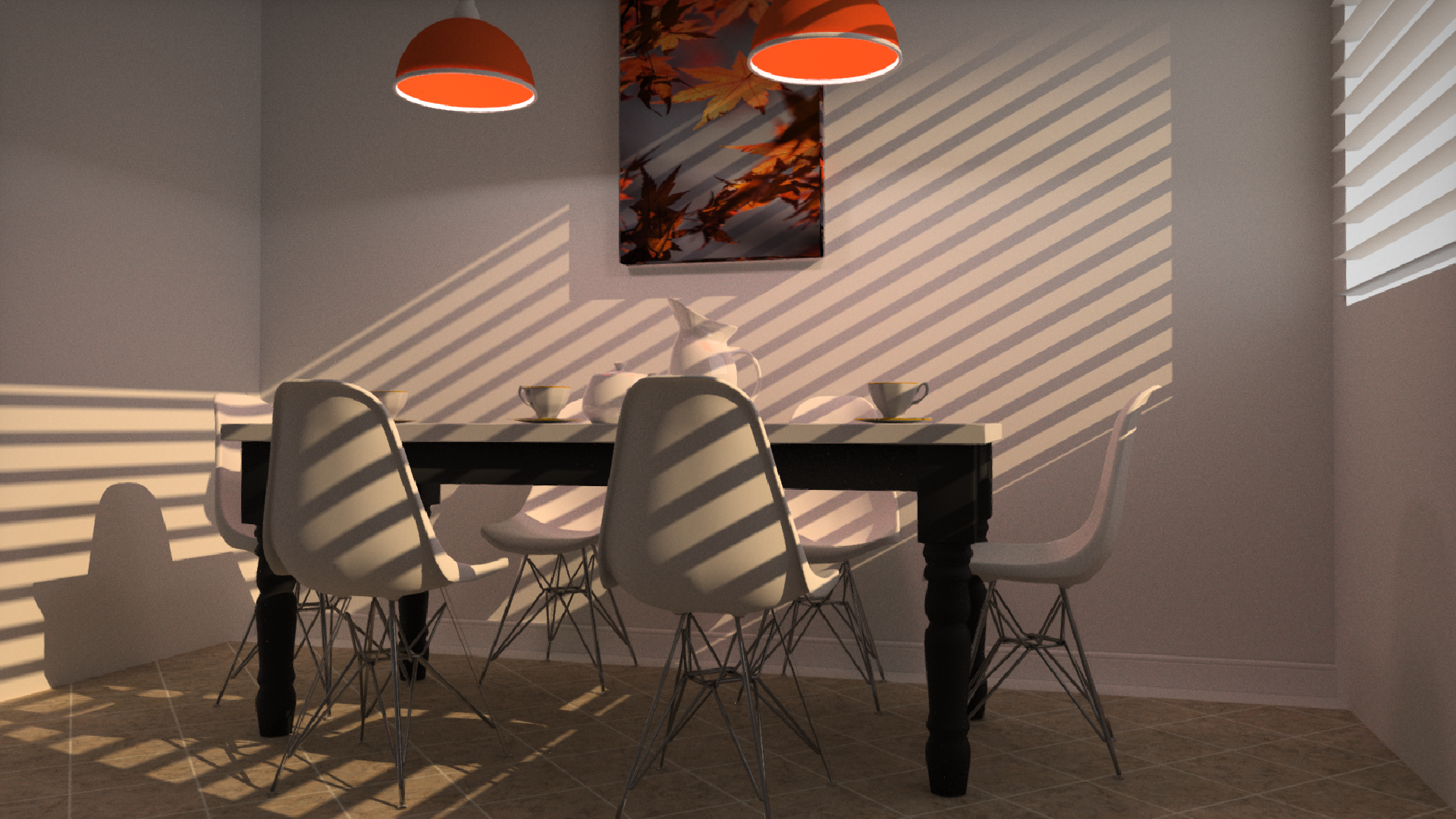
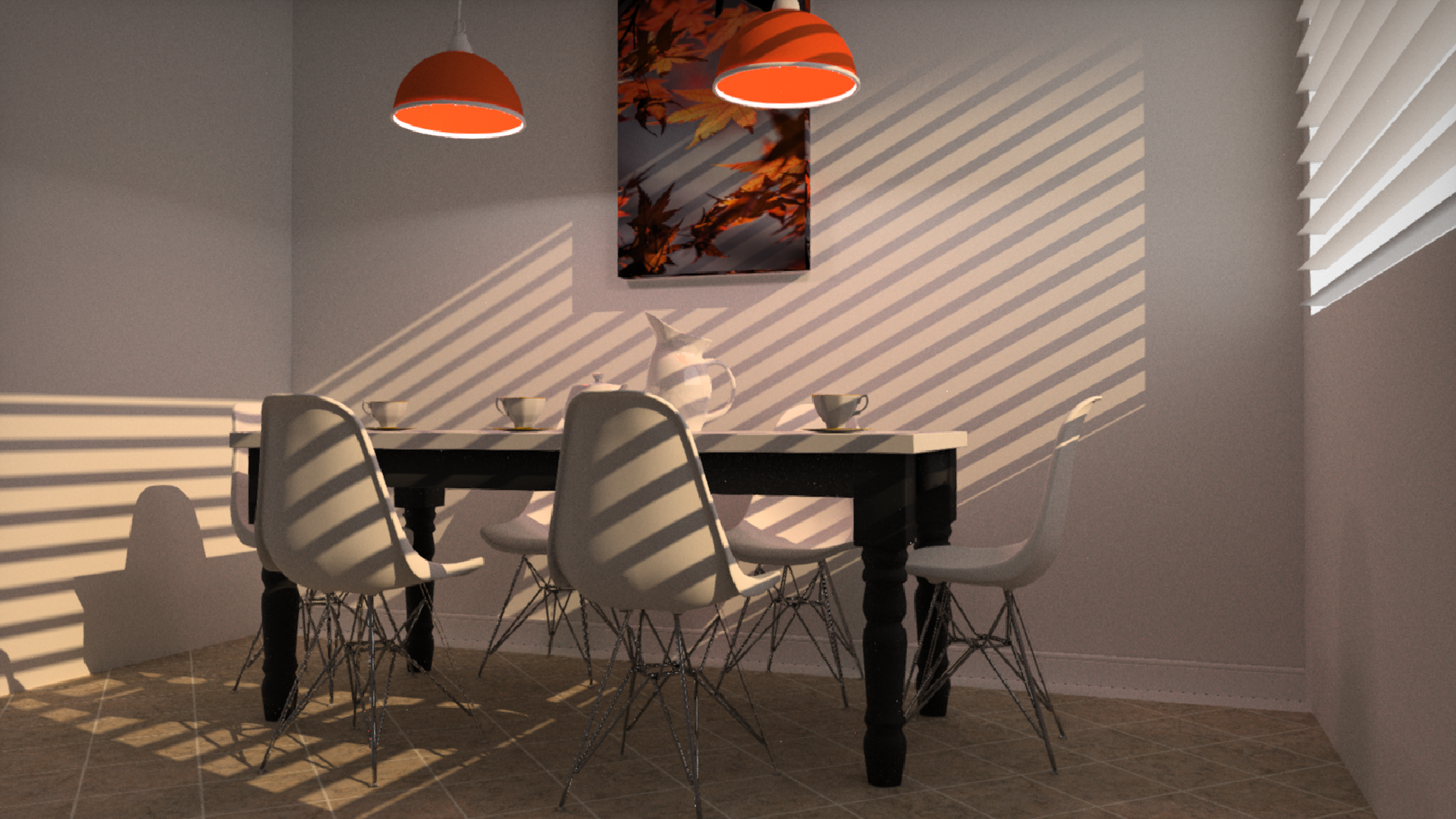

The outlines of the shadows and the objects are on par with the unoptimized version. The problem lies in the reflections of the chair’s legs and the outline at the bottom of the wall.
The uniform fog part was a bit tricky because I implemented a naive version and it required a big number of scatter events and paths to evaluate, otherwise we would have a very noisy image.
The methodology is that for each ray in a transport path:
- we intersect it with the scene as we normally would,
- we produce a probability to hit a particle based on the distance that it will travel,
- we generate a random number and see if there is indeed an intersection with a particle,
- if there is no intersection with a particle, we continue normally,
- if there is intersection:
- we generate another random number (0, ray_length) to determine the position of the particle along the ray’s direction,
- we replace the previous surfel with the particle,
- we continue with the shading as normal,
- when the scattering is calculated, we generate a new random ray on the unit sphere around the intersected particles.
The noisy image stems from the fact that we use a lot of uniform random numbers and we don’t perform any importance sampling for the scatter directions. Below you can see some generated images with the uniform medium implemented.


Noticing the differences in the quality of the fog, the quality increased as the paths and scatter events are increased too but so does the rendering time. Let’s not forget that everything is running on the CPU still.
This project had very little guidance again but I assume that if someone has made it at this point, they are determined to finish the assignments so they will search and find what they need. Looking at the rendering of the fog makes the time spent well worth it.
7. Ray marching on the GPU
And that brings us to the last project which involves Ray Marching on the GPU and the Sphere Tracing approach in particular. The whole project is writing GLSL code that is exclusively run on the GPU, so the code is only written in shaders. The “Ray Marching” chapter does an insanely good job at explaining the method to absolute beginners and it doesn’t require reading any of the previous chapters.
Developing the ray marching code from scratch can be a pain at the start because we start with very simple shapes but our code can break down and not be extendable when it is time to build very complex scenes. This was my experience as it was the first time doing something like this and supporting the first 3 primitives and combining them to have something meaningful took many iterations of rewriting my GLSL API to finally be at a state where it is usable. You can find the code in my public repo.
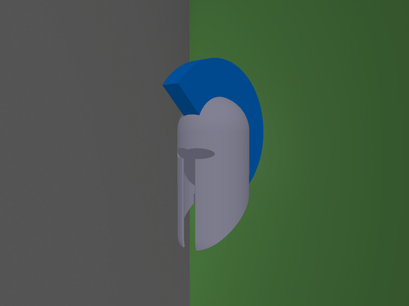
For my “assignment” I spent more time on the reducing the code complexity to easily support new shapes in matter of minutes and not developing quality shading. So, my creation is an ancient Greek helmet and below you can see the process of using primitives and operations with them to finally show an actual object.
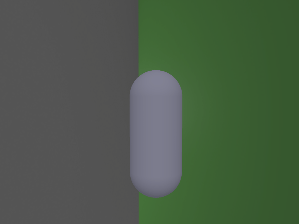
The process I followed to create such an object with ray marching and sphere tracing is as follows:
- Add a capsule for the base shape.
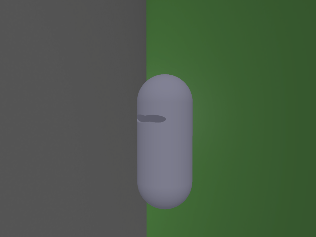
- Add an ellipsoid for the first eye socket. (union operator)
- Add a second ellipsoid for the second eye. (union operator)
- Hide the ellipsoids and the area where they meet the base shape capsule. (subtraction operator)
- Add a rectangle for the nose and mouth region. (union operator)
- Hide the rectangle and the area where it meets the base shape capsule. (subtraction operator)
- Add a second smaller capsule inside the base shape capsule. (union operator)
- Hide the smaller capsule and the area where it meets the base shape capsule. This makes the base shape appear as hollow. (subtraction operator)
- Add a plane that splits a region in half. (union operator)
- Hide the plane and everything on its other side. (subtraction operator)
- Now for the hair, add a disc. (union operator)
- Cut it using a plane. (subtraction operator)
- Cut it again using the base shape capsule. This cut is needed so that the hair is not visible inside the helmet. (subtraction operator)
- Add the hair on top of the base shape. (union operator)


Closing remarks
And this was my experience and trip through the Graphics Codex! I have to say that it really helped me solidify my knowledge about a lot of stuff and the writing of the chapters is very well suited for everyone.
What I wanted was a bit more guidance in some of the projects as I mentioned above but a determined person can overcome that lack and produce something valuable.
If you don’t know if you should pick this learning resource, I really suggest you do and play a lot with each project!

I am getting into environment error where I don’t see much color. For example, the first yellow cube example shows up black on my screen. Did you see any such issue? Is there any group where one can ask for help with Graphics codex projects?
LikeLike
Hello. Unfortunately I didn’t have any issues setting up the projects. I also don’t believe there is any active group currently because these projects were meant to be undertaken by undergraduate students at university courses. So, the rest of us are pretty much on our own
LikeLike